Creating an ICD
Create an Action
The first step to creating an ICD is to create an action and corresponding working branch. First, navigate to the Connections Page. You will then need to select the Product Line branch you would like to create your working branch from. If there is no product line branch available, contact your MIM administrator.
Click the Create Action button on the right to begin creating an action.

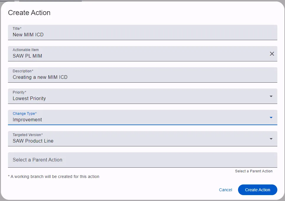
Fill in the fields in the dialog as needed. Some notable fields are:
- Actionable Item - There is likely a MIM actionable item available in your instance. If not, contact your administrator.
- Targeted Version - This field is what determines which branch your working branch will be based on.
- Parent Action - Set a parent action if you would like this new action to be related to an existing action for tracking purposes.
Once the action is created, you will automatically change to your new working branch.
Enable Edit Mode
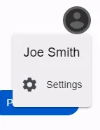
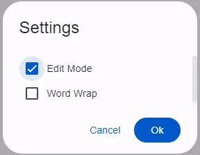
In order to make changes on this new branch, you will need to turn on edit mode. Click your avatar in the top right corner of the screen, open the settings, menu, and enable edit mode.
Create Artifacts to Populate Dropdowns
A lot of the dropdowns in MIM are populated by Artifacts that are stored in the database. These generally only need to be created once per Product Line branch and then they can be used across all branches and ICDs that are created from the Product Line. To create these Artifacts, you must be a MIM Admin, or contact your admin.
Navigate to the List Configuration Page, and add the values you’ll need for your ICD.
Create a Transport Type
If the product line branch doesn’t already have the Transport Type for your ICD, you will need to create one on the Transport Types page.
Create Nodes
To create a node, right click anywhere in the area below the branch selector to open a menu with the options to create nodes and connections.
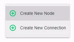
Select Create New Node to open the dialog and fill out the fields.
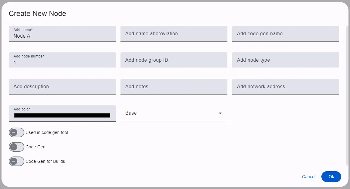
Click Ok to save your changes and create the node.
Create a Connection
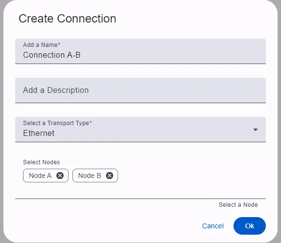
Once a transport type and two or more nodes have been created, you can create a connection. Right click either on a node, or on the canvas similar to how the node was created.
Create a Message
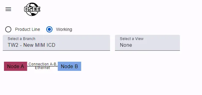
Click on the Connection’s label that is connecting the nodes to navigate to the connection’s message table.
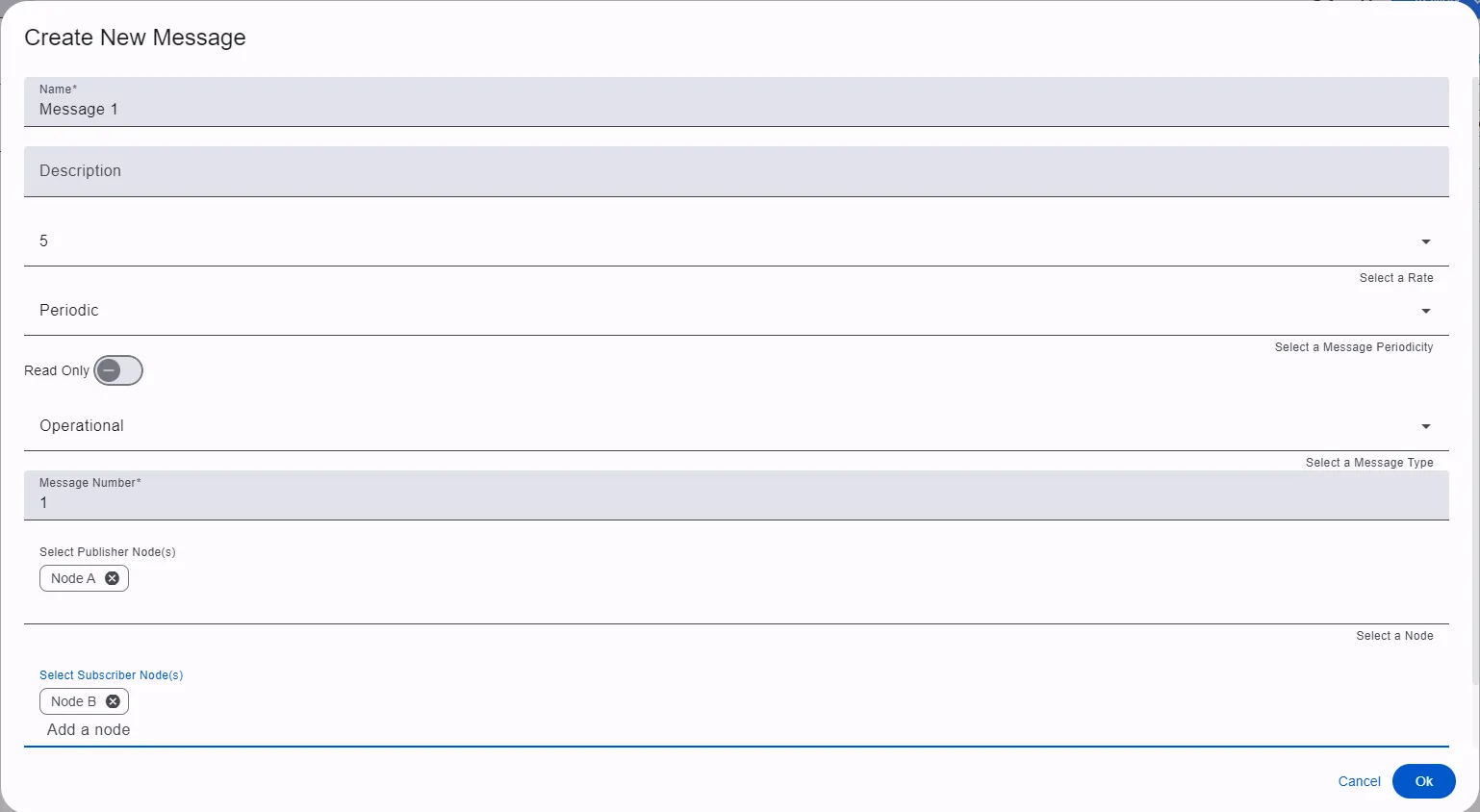
To begin creating a message, click the green + button at the bottom of the table. Populate the fields in the dialog and click Ok to create the message.
The number of nodes that can be selected as publishers and subscribers are limited based on the connection’s transport type settings.
Create a Submessage
Once the message is created, expand the message by clicking the drop down arrow to the left of the message name. This will expand the submessage table under the message. Once this is expanded, the Add Submessage to: button becomes enabled, with an annotation noting the number of messages available to add submessages to.

Submessages can only be added to messages that are expanded.
Click the newly enabled button and select the message you would like to add the submessage to.
Here you will be given the option to create a new submessage, or use an existing one. We will be creating a new submessage for this example. Populate the fields and click Ok to create the submessage.

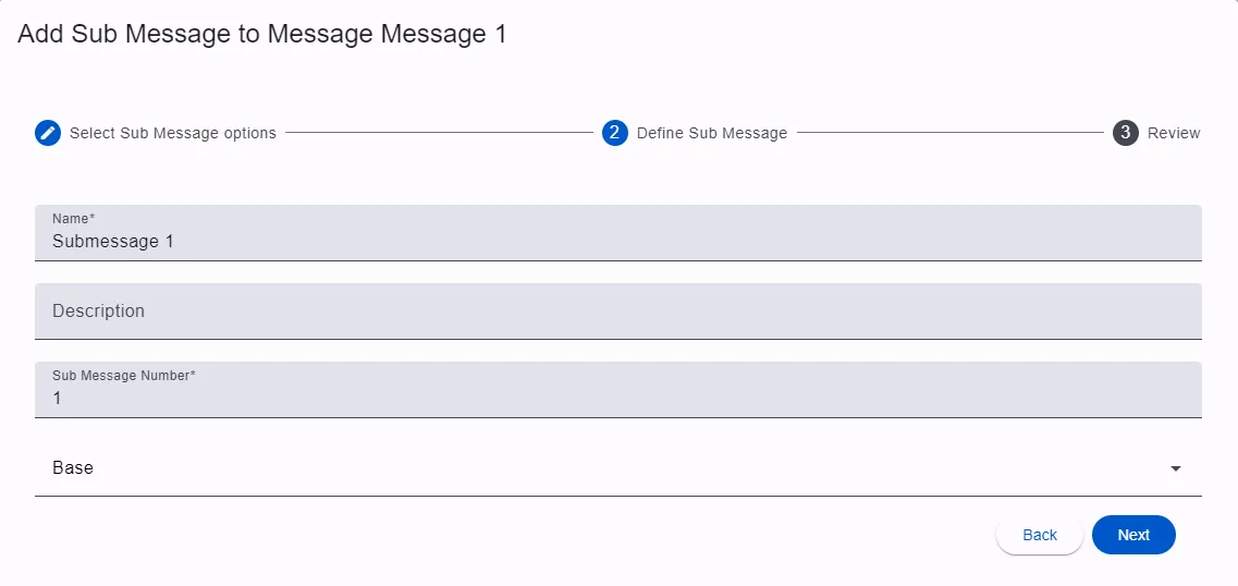
Now you will see the submessage in the table.

The yellow-colored submessage seen here is an autogenerated message header. MIM is able to create these headers for you if your project needs them. This is configurable from the connection’s transport type.
Create a Structure
From the submessage table, click the Go To Message Details button in the submessage row to open the Structure table. This table works in a similar way to the Message table. Click the green + button to begin creating a structure.
Similar to creating a submessage, you can choose to create a new structure or reuse an existing one. We will create a new structure for this example. Populate the fields and click Ok to create the structure.
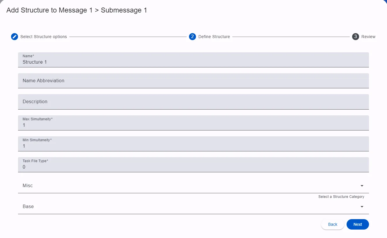
If the transport type being used for your connection is set to enforce byte alignment, you will likely see some yellow autogenerated
Insert Spareelements in the table. These are there to let you know that the structure is currently not byte aligned and show the number of bytes needed at that location in order to become byte aligned.
Create Elements
Once the structure is created, expand the structure by clicking the drop down arrow to the left of the structure name. This will expand the element table under the structure. Once this is expanded, the Add Element to: button becomes enabled, with an annotation noting the number of structures available to add elements to.
Elements can only be added to structures that are expanded.
Click the newly enabled button and select the structure you would like to add the element to.
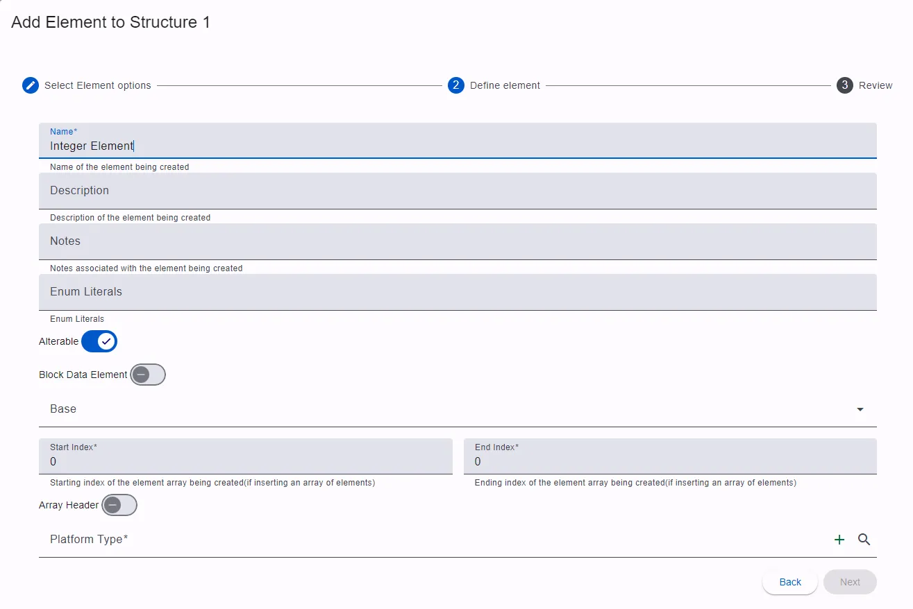
Similar to creating submessages and structures, you can choose to create a new element or reuse an existing one. For this example we will create a new element.
First, we will create an element generically named Integer Element that has a range of 0-100 meters. There are a lot of fields here, but for now we will just populate the name and platform type fields. The first time an element is created, there will be no platform types available, so we will create a new one by clicking the + button on the right side of the platform type field.
Select Integer for the logical type and click Next. Populate the fields and click Next to review and finish creating the platform type.
There is a
Nextbutton for the outer element dialog, and aNextbutton for the inner platform type dialog. Be sure to click the inner platform typeNextbutton.
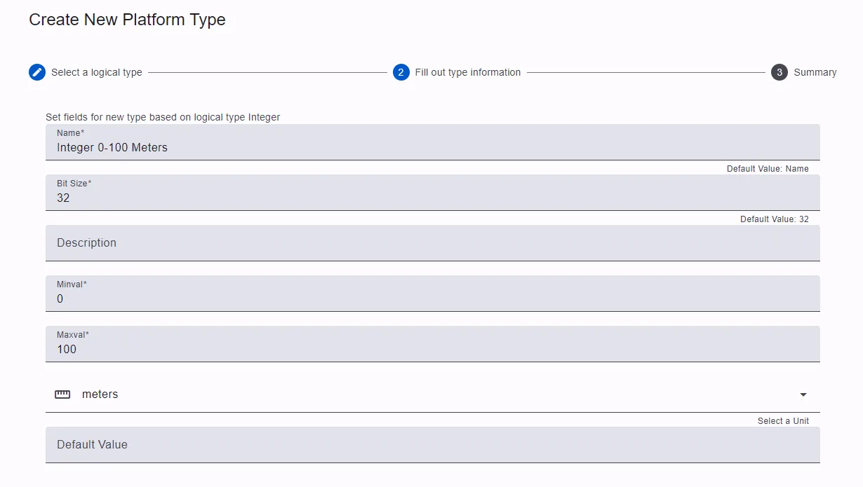
Click Next to review and finish creating the element.
Using the same process, more elements were added for this example as seen here:
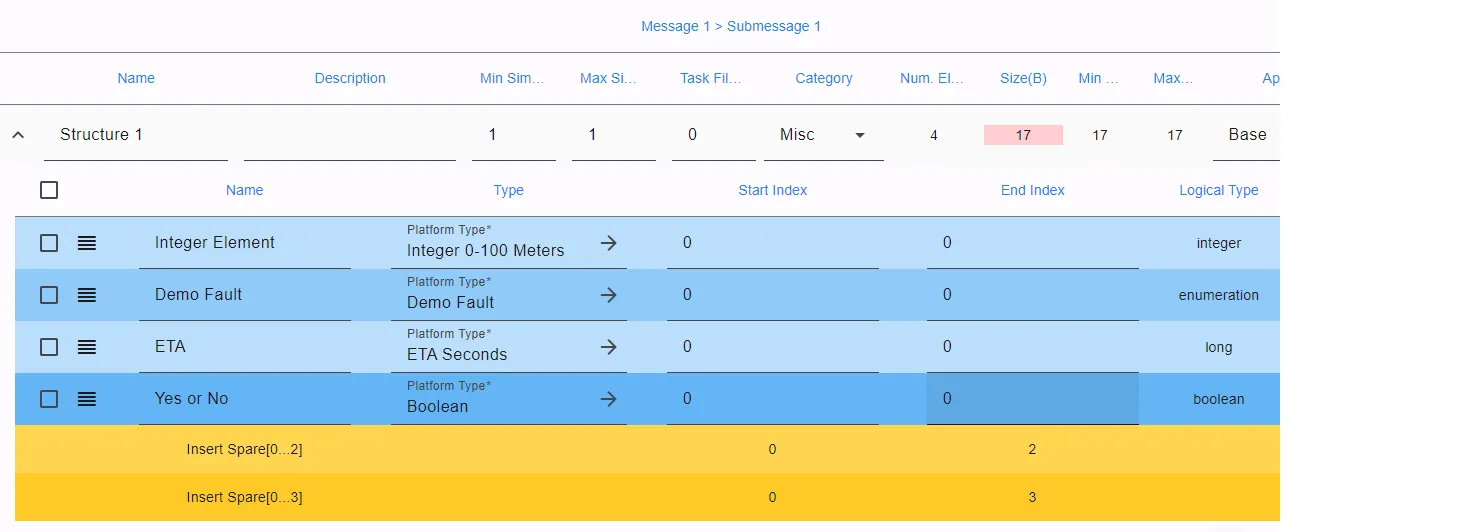
One notable addition is the Yes or No boolean element with the start index set to 1 and end index set to 4. This represents an array of elements, which are very useful when the ICD requires many duplicate elements in a row with only the array index being different between them.
As you can see. There is an autogenerated Insert Spare element at the bottom of the table. This is here because the structure is not byte aligned on 8 byte boundaries as the transport type requires. To resolve this, another 4 bytes must be added. In this example, I simply extend the Yes or No array to end at index 8, but another element could have been added to fill this space as well. A common way to pad out bytes is to insert “Spare” elements into the structure.

Committing to the Product Line
Now that the ICD is complete, the working branch can be merged into the Product Line to be shared with the rest of the organization. In the top right corner of the page there is an Action State button as seen below. Click that and transition the branch through its various states until it can be committed.
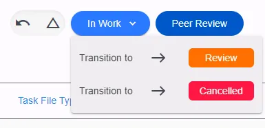
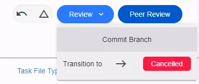
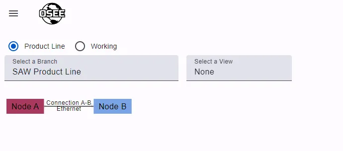
Once the branch is committed, the page will automatically navigate to the Product Line branch.
What Next?
Congratulations! You just created your first ICD using MIM. Next, take a look at these topics:
- Creating Revisions to Existing ICDs
- Genering Reports
- Product Lining
- Traceability
